Using the bodies selector select one or more bodies in the graphics window. Show me how to select sketch geometry select objects enclosed by selection window position the pointer slightly above and to the left of the left most object to select.
 Autodesk Inventor Move Rotate 3dn Ninja
On the freeform body select one or more freeform edges to modify.

Inventor selector box graphics window. Choose faces in the dialog box and then select the faces to exclude from curve generation in the graphics window. You can select multiple toolbodies. Using the profile selector click in the graphics window to select one or more profiles sketch geometry or text to emboss or engrave.
Do one of the following. Scales the solid using separate x y z scale factors. Using the base selection arrow choose the base solid body in the graphics window.
Double click an edge to select a loop. Click apply or ok. The edges option is active in the dialog box.
In the graphics window select the solid to scale. For an unconstrained move click inside one of the value boxes for x y or z and then click and drag the move preview image. Use the pointer to window select objects in the graphics area.
In the mini toolbar select a modifier. In the graphics window select the model or sketch curves for the selected freeform body edges to conform to. Using the bodies selector select one or more bodies in the graphics window.
Optionally you can exclude geometry from silhouette curve generation by doing the following. Combine solid bodies note. In the dialog box click target.
Click apply or ok. In the application options dialog box sketch tab deselect autoproject edges during curve creation. For an unconstrained move click inside one of the value boxes for x y or z and then click and drag the move preview image.
In the application options dialog box sketch tab deselect autoproject edges during curve creation. Using the toolbody selection arrow select the solid bodies to combine with the base. To make selection easier turn off automatic projection.
For an unconstrained move click inside one of the value boxes for x y or z and then click and drag the move preview image. The combine command is available in multi body part files only. Click apply in the mini toolbar.
In the free drag area of the move bodies dialog box enter x y and z offset values. In the graphics window drag the manipulator handle or enter a value in the input box. In the free drag area of the move bodies dialog box enter x y and z offset values.
Do one of the following. The selector in the dialog box changes to direction. Using the bodies selector select one or more bodies in the graphics window.
Using the profile selector click in the graphics window to select one or more profiles sketch geometry or text to emboss or engrave. In the free drag area of the move bodies dialog box enter x y and z offset values. The number of toolbodies selected displays in parentheses.
Available in part sketch assembly assembly sketch drawing drawing sketch presentations and dynamic simulation. Select a work plane planar face edge or an axis to specify the pull direction. Click 3d model tab modify panel combine.
Do one of the following. To make selection easier turn off automatic projection. Scales the solid using a single factor.
Click apply or ok.
 Autodesk Inventor 2014 By Stroitelen Inzhener Issuu
 The 50 Best 3d Modeling Cad Software Tools Pannam
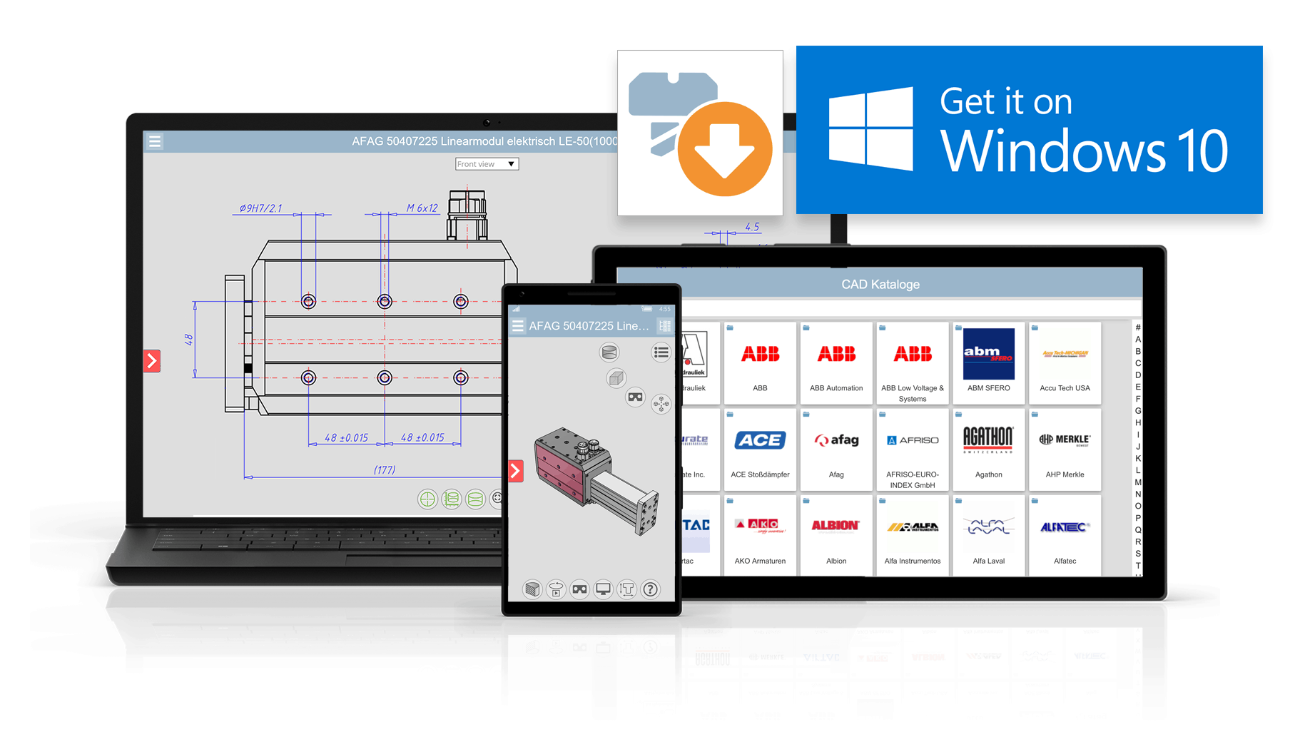 First 3d Cad Model App For Windows 10 Is Now Available
Inventor 2019 1 Update Adds New Features To Hole Command
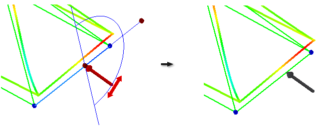 Applying Loads Inventor Products Autodesk Knowledge Network
 About Property Panels Inventor 2020 Autodesk Knowledge
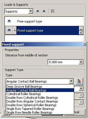 Inventor Shafts And Splines Augi The World S Largest Cad
What S New In 2019 Ironcad Cad Software Solutions
 Autodesk Inventor Move Rotate 3dn Ninja
 Box Selection In Solidworks 3d Cad
 Linux Journal May 2012 Issue 217 Acm Digital Library


